The Worthing HO Racing website is licensed under a Creative Commons Attribution 3.0
Unported License (except where otherwise noted) 2012-


WHO Driver Stations
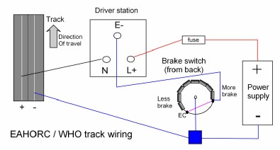
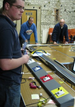
Driver stations are where we plug in our controllers and adjust the brake settings. The WHO stations are encased by Mike’s beautiful carpentry (see right), but underneath, this is the wiring:
WHO Racing driver stations are wired the same as those at EAHORC and the basic wiring
is as per the BSCRA track wiring section, with the track wired positive to the left
rail -
The adjustable brakes are based on the Rotary Diode Brake Kit at AB Slotsport. The main difference being this is attached on the driver station side of the brake wire, rather than in the controller. There is also a jump lead that puts an 'Electronic Controller' next to minimum brakes.
Brake switch build
Parts list (per switch):
1 x Rotary switch: 1-
1 x knob to fit 6.35mm shaft.
8 x 1N4001 Rectifier Diodes
Plus some assorted stranded wire (you could use get the same colours as on the diagram) and I used single core for the EC jumper.
The trickiest thing is making sure the diodes are soldered sufficiently. Use flux on the joins and then a hot iron and plenty solder.
When Robin & me tested the switches we attached the track wires straight to a car, revved it and stopped. The motor (and gearing) should stop dead on the maximum brake settings and increasingly loosen up as less brake is applied.
You need to start on maximum brakes (the first switch position) and then add in a diode each time. If the brake stays the same between two settings (and all the following ones), then the solder on that connection needs looking at.
-


The WHO Racing Driver Stations